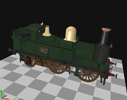
 | In this tutorial we will use the GWR Class 517
0-4-2 steam locomotive model provided by Paul Gausden. It can be
downloaded
here.
The first step is to run the Train Simulator Wizard and test the model
in Train Simulator.
If you are using GWR Class 517 model you should click "Reset" when asked to
identify parts. This will ensure that you have everything named using
the wizard's standards.
|
|
 |
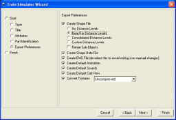
 | Creating distance levels can be as simple as
selecting either the Standard Distance Levels or
Automatically Simplified Distance Levels export preference. If you select one
of these 3DCrafter will automatically create distance levels.
Standard Distance Levels will create simplified models to be
seen beyond 100 meters and beyond 400 meters. To do this it removes
parts smaller than .5 meters in width/height/length from the model at
100 meters and removes parts smaller than 2 meters in
width/height/length at 400 meters.
Automatically Simplified Distance Levels removes parts in the
same way as Standard Distance Levels but also reduces the
complexity of the parts where possible.
Note: The Retain Sub-shapes option is only intended to be used
by those creating signals.
|
|
|
 | The Custom Distance Levels option allows you
to manually create your own simplified versions of your model. This
will be the main focus of this tutorial.
The setup for custom distance levels is quite different from the
setup, described above, for
automatic generation of distance levels.
In this tutorial we will be creating multiple versions of the same model. Each model
will be progressively simpler.
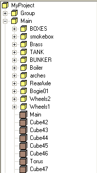
The Custom Distance Levels option requires that each shape have
a unique name. To create unique names select your entire model
(right-click on a shape in the root group and choose "Select
Hierarchy"), and run the Create Unique Names
plug-in. If you do not have 3DCrafter Pro you will need to manually
create unique names for all shapes. The Wizard will warn you if it
finds that you do not have unique shape names.
|
|
|
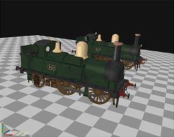
 | The next step is to create a duplicate of your
model. Select the full hierarchy of the model and then copy and paste
it to the scene. It will copy over top of the original model so grab
the model by its root shape and move it over so you can see both
models. |
|
|
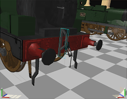
 | Delete all of the small parts from the duplicated
model. |
|
|
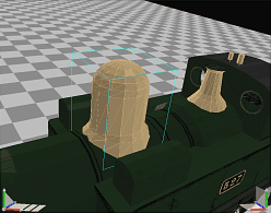
 | Use the Reduce operation on any parts that are
complex and solid. You may want to run the Crease operation after
reducing since the reduced parts often become too creased.
There is no need to merge triangles after applying the Reduce
operation. |
|
|
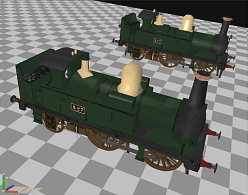
 | We have our first distance level model.
Rename its "Main" group to "Main.20". This will make this version
of the model become visible at distances of 20 meters and higher.
Normally 100 to 300 meters would be more reasonable but we would like to
easily see the changes in distance levels when viewing our model in
Train Simulator to ensure correctness. |
|
 |
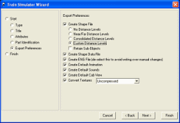
 | Run the Train Simulator Wizard with Custom
Distance Levels selected. |
|
 |
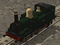
 | Here is our distance level in Train Simulator. If
you compare to the next picture you will see obvious differences.
Remember that we are viewing this model from 20 meters. When viewed
from 100 or more meters there will be no differences noticeable. |
|
|
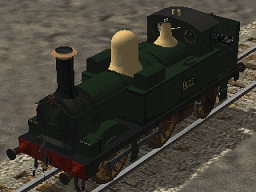
 | The original model. |
|
 |
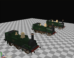
 | Copy and paste the reduced model to create a third
distance level. |
|
 |
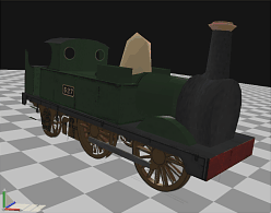
 | Again, delete shapes and reduce until you have a
simple model.
Rename its "Main" group to "Main.30". This will make this version
of the model become visible at distances of 30 meters and higher.
Normally 700 meters would be more reasonable but we would like to
easily see the changes in distance levels when viewing our model in
Train Simulator to ensure correctness.
Export and view the model in Train Simulator to ensure that the model transitions
properly through the distance levels.
Once you are satisfied rename the "Main.20" group to "Main.200" and
the "Main.30" group to "Main.700" and export to Train Simulator.
We now have a model with three distance levels. |
|
 |


